
Engine & Diagnostics
Engine Management Strategy and Fuel Trim
How the engine computer decides how much fuel to inject, what short-term and long-term fuel trim really mean, and how to read them to track down rich and lean problems.
Back to Basics
Troubleshooting engine performance problems can be difficult, especially when there isn't enough diagnostic information. Sometimes it's hard to decide which information is essential and which can be ignored. The key is to go back to basics and keep it simple: return to the fundamental theory and the basic data.
Fuel and spark calculations are, in most cases, influenced by relatively few inputs. In fact, the base calculation relies on only two: engine speed and engine load.
Apart from these two, only four other inputs have a significant effect on fuel injection, and a smaller effect on the ignition map: the engine coolant temperature sensor, the intake air temperature sensor, the throttle position sensor and the lambda (oxygen) sensor.
Analyzing the data becomes much simpler once you know these six inputs, their parameters and their normal values.
The Six Main Inputs
In order of importance:
- Engine load: a calculated value derived from the mass of air entering the engine, using a specific algorithm, together with throttle position data.
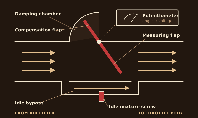
- Vane air flow meter
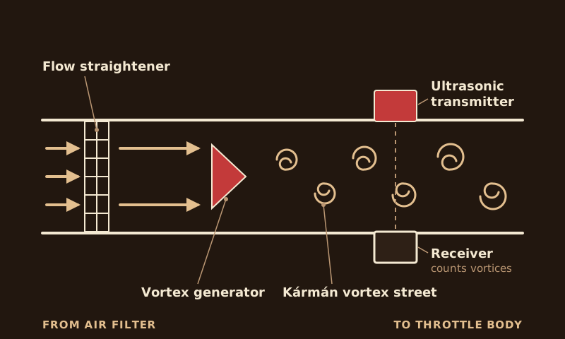
- Karman vortex air flow meter
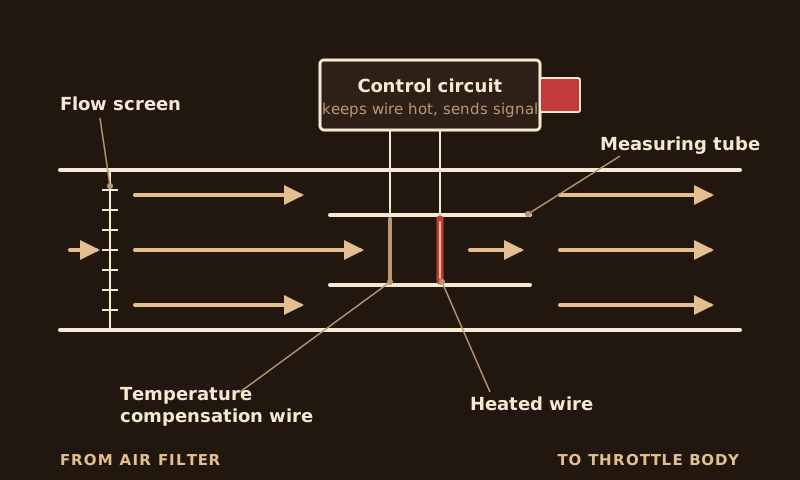
- Mass air flow meter (hot wire or hot film)
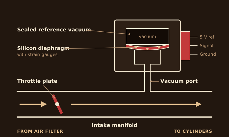
- Manifold absolute pressure (MAP) sensor
- Engine speed
- Engine speed sensor
- Coolant temperature
- Engine coolant temperature sensor
- Throttle position
- Throttle position sensor
- Closed throttle switch
- Intake air temperature
- Intake air temperature sensor
- Exhaust oxygen
- Oxygen sensor
How the Air Metering Devices Work
The engine load input comes from one of four kinds of sensor. Each measures the air going into the engine in a different way.
Fuel Trim
To understand oxygen sensor feedback and how the parts relate, a short review of fuel injection theory helps.
Injection Duration: Theory
Injection duration is a function of three factors:
- Basic injection time.
- Injection duration correction for engine operating conditions (for example, acceleration).
- Injection time correction for battery voltage (in newer vehicles).
Basic injection duration is based on engine load, engine speed, and a correction factor called fuel trim. The correction for engine operating conditions is based on the inputs below. These adjust the basic injection duration so it responds to changing engine conditions.
- Engine coolant temperature (ECT)
- Throttle position (TPS)
- Intake air temperature (IAT)
- Exhaust oxygen (O2)
The battery voltage correction is applied to the final injection time. Its job is to compensate for injector opening time, which varies with battery voltage.
Calculating Basic Injection Time
The first step in deciding how much fuel to inject is calculating the initial injection duration. Basic injection time is a function of:
- Engine load (VAF, MAF, MAP)
- Engine speed
- Long-term fuel trim (LONG TRIM)
Basic injection time is the best educated guess the engine computer can make about how much fuel the engine needs. In general it is quite accurate, within about ±20% of the injection time actually required. Once it is within range, the computer fine-tunes the final value from the oxygen sensor reading.
Oxygen Sensor Correction
The oxygen sensor reading varies with many factors. If the correction needed is relatively small, say under 10%, the computer can correct the mixture easily. When a large correction is needed, it's harder for the engine computer to correct the mixture.
For large corrections, the computer has a memory that learns the value so it can correct, or "trim," the mixture by adjusting the basic injection time. This keeps the oxygen sensor reading within an acceptable range, so the computer can keep making corrections.
How Fuel Trim Affects Injection Time
Fuel trim is the amount of injection time compensation, in percent, based on the oxygen sensor reading. There are two types: long-term fuel trim (LTFT) and short-term fuel trim (STFT).
Long-term fuel trim is part of the basic injection time calculation. It determines how accurate that calculation is and how close it comes to the target mixture. It is a learned value that changes gradually in response to conditions outside the system's normal operation, such as engine wear, air leaks or changes in fuel pressure.
Short-term fuel trim is the amount added to (or subtracted from) the basic injection time. The oxygen sensor tells the computer how close it is to the target air/fuel ratio, and short-term fuel trim corrects accordingly.
Short-Term Fuel Trim (STFT)
Short-term fuel trim is a temporary correction to the fuel quantity that changes with every oxygen sensor cycle. Under normal conditions it fluctuates slightly and rapidly around the ideal value of 0% correction, and it is active only in closed-loop control.
It is a parameter in the OBD-II data stream, shown on the scan tool screen. Its active range is ±12% on Euro 4 systems and ±20% on Euro 3 systems, but under normal driving it rarely goes past ±7%. The value is held in the computer's volatile memory and is erased every time the ignition is switched off.
Short-term fuel trim responds to changes in oxygen sensor readings. If the basic injection duration produces a lean air/fuel mixture, short-term fuel trim adds fuel. If it produces a rich mixture, short-term fuel trim removes fuel.
When short-term fuel trim hovers close to 0%, the basic injection setting is producing a mixture very close to stoichiometric, without significant correction from the oxygen sensor.
Long-Term Fuel Trim (LTFT)
Long-term fuel trim is a parameter in the OBD and OBD-II data streams. It is a more permanent correction to fuel delivery because it is part of the basic injection time. It changes more slowly, and its operating range is ±20%.
If short-term fuel trim stays beyond a set value, for example ±10%, for longer than a set time, the correction is moved into long-term fuel trim, which changes the basic injection time. That brings short-term fuel trim back into its effective range.
Short-term fuel trim affects injection duration only in closed loop. Long-term fuel trim changes the basic injection time, so it also affects injection when the system is not in closed loop.
The correction is stored in RAM that stays powered with the ignition off, so it is not erased when the engine is shut down. Using long-term trim, the fuel system can correct the mixture even during warm-up or at wide-open throttle.
In OBD data, long-term trim appears as the target air/fuel ratio (TARGET). On vehicles without a data stream, it appears as a learned voltage value (LVF).
Fuel Trim in Action: Four Examples
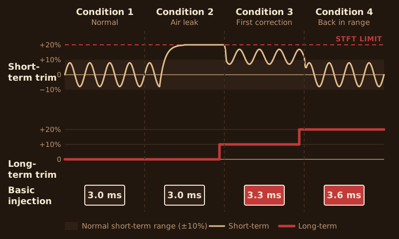
Condition 1: Normal operation
The system is operating in its normal range. Based on engine load and speed, the calculated basic injection time is 3 ms. Short-term fuel trim fluctuates within ±10%, and the oxygen sensor works normally.
Condition 2: Intake air leak
An air leak into the intake manifold. Basic injection time stays at 3 ms, because none of the factors that set it have changed.
- The extra air makes the engine run lean, and the oxygen sensor reports a lean mixture.
- Short-term fuel trim tries to correct it but hits its limit without bringing the system back into range.
- The computer learns the value, adjusts long-term fuel trim, and changes the basic injection time.
Condition 3: First long-term correction
Continuing from Condition 2, after the computer changes long-term fuel trim. The air flow meter and RPM readings are unchanged, but basic injection time has been changed by 10% and is now 3.3 ms.
- The fuel system delivers enough fuel for the oxygen sensor to return to almost fully normal operation. The sensor works, but slightly slower than usual, and short-term trim raises its compensation to 15% to make up for it.
- The computer learns that it needs to raise long-term trim further to bring short-term trim back to normal.
Condition 4: Back in range
The result of the second mixture change. The air flow meter and RPM readings are still unchanged, but basic injection time has been changed by another 10% and is now 3.6 ms.
- Basic injection time is again within about 10% of what is actually needed.
- The oxygen sensor works normally, in both voltage and response speed.
Target Air/Fuel Ratio
Long-term fuel trim, target air/fuel ratio and learned voltage value are ultimately the same thing, but they are displayed differently in OBD data. Learned voltage and target air/fuel ratio are shown as a voltage from 0 to 5 V. The value changes in steps of 1.25 V, with a midpoint of 2.5 V.
A learned voltage of 2.5 V means basic injection time is within ±10% of the injection time needed for a stoichiometric mixture. If basic injection time is further off than that, the learned voltage changes.
A lower voltage means shorter injection to compensate for a rich mixture. A higher voltage means longer injection to compensate for a lean mixture.
Using Fuel Trim in Diagnosis
When troubleshooting engine performance, one of the first checks is the oxygen sensor closed-loop system: is the engine running in closed loop, and is the computer making an excessive correction for a mixture that is too rich or too lean?
When to Use Fuel Trim Data
Fuel trim outside the desired range is not the problem itself. It tells you another problem exists, and it can help lead you to the real cause. Fuel trim data is typically used to:
- Do a preliminary check of the feedback system
- Troubleshoot emissions problems
- Troubleshoot engine performance problems, especially ones that happen in open loop
- Verify the feedback system after a repair
Subsystems That Affect Fuel Trim
Once you know the symptom and can confirm the mixture is abnormally rich or lean, it is relatively easy to list every subsystem that could cause it. Check each one for proper operation. The table below lists likely causes.
| Rich mixtureNegative fuel trim (computer is removing fuel) | Lean mixturePositive fuel trim (computer is adding fuel) |
|---|---|
| High-altitude operation (vehicles without built-in altitude compensation) | Low fuel pressure |
| Fuel contamination in the engine oil | Intake manifold air leak |
| Saturated or faulty charcoal canister (EVAP) system | Exhaust leak upstream of the O2 sensor |
| Excessive exhaust gas recirculation (EGR) flow | Worn throttle shaft |
| Leaking fuel valve | High oxygen content in the fuel |
| Fuel pressure too high | Clogged or partially clogged injector |
| Leaking injector | Water in the fuel |
| Faulty secondary air system |